

Table of Contents
Stepper motors are the unsung heroes behind the precise movements of 3D printers, CNC machines, camera sliders, robotic arms, and countless other automated systems. Because they rotate in defined steps, they are suitable for any application that demands precise positioning.
However, stepper motors are the subject of more questions than answers-as one might expect with a beginner, or even a seasoned user, faced with advanced levels of motion control versus resolution. These questions go beyond engineering curiosities; considering the answers to them assures your stepper motor works safely, efficiently, and reliably.
In this article, we will discuss five typically asked stepper motor questions and provide clarity, tips, and practical information to help you understand, work with, and maintain your motor like a pro. Whether it is a DIY project or fine-tuning industrial machinery, these answers will show the way.
Quiz 1. Can a 48V stepper motor be powered by a 12V power supply?
On first consideration, matching the voltage of a motor with the voltage of the power supply seems simple, but stepper motors are unlike an elementary DC motor. Most current stepper systems use current-controlled drivers (or microstepping drivers) to control the coil current rather than coil voltage. Rating a motor at 48V generally means the motor coils will have high inductance and low resistance, such that they allow rapid changes in current and smooth microstepping.
Why is rated voltage less important with current drivers
Current-controlled drivers provide higher supply voltage to overcome coil inductance and quickly establish the specified current. It is possible, for instance, that a driver had to supply 48V at the start to charge up the coils fast, then chop that current down to the actual desired level. Limiting the voltage to 12V means that voltage headroom is diminished and the current, therefore, ramps up more slowly, with the result being that at some given step frequency, the maximum speed and torque diminution becomes evident.
Consequences of undervolting
● Reduced maximum speed: the limited voltage becomes unable to overcome inductive reactance fast enough at higher step frequency, causing the current to never reach the target level before the next step, hence the torque starts to decline.
● Lower torque across the board: Even at low speeds, the motor may never reach full rated current, so torque is permanently reduced.
● Driver detection issues: Some drivers expect a minimum supply voltage to function correctly. Falling below that threshold can cause erratic behavior or failure to initialize.
Under what circumstances might it work?
1.Low-speed, low-torque uses: Should your application call for just slow, gentle movement, a 12 V supply might do.
2.Short movements or intermittent use: It might run for quick impulses of motion if the motor has time between moves to build current.
Quiz 2. Why does the system not run after the stepper motor is powered on?
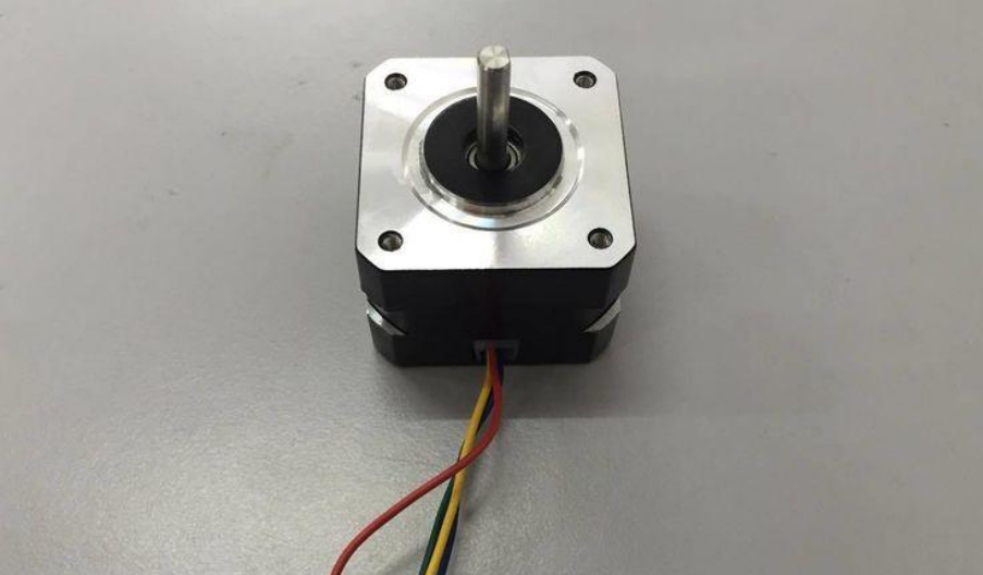
Nothing is more frustrating than powering up your system only to see no movement. Several things could have prevented the stepper motor from spinning: electrical issues, mechanical issues, or firmware issues, even though the motor seemingly appears to have power.
Electrical causes
1. Incorrect driver wiring
● Coil misconnection: Stepper motors normally have four, six, or eight wires. If the coils are not properly paired and connected to the driver terminals (A+, A–, B+, B–), the driver will not energize them in the correct sequence for motion.
● Power/GND reversal: Reversing the V<sub>+</sub> and GND terminals on the driver may damage or stop it from functioning.
2. Insufficient supply voltage or current
● Underrated power supply: A power supply not able to meet the current demand will drop the voltage under load. Instability or driver shutdown due to under-voltage protection could be induced.
● Unconfigured current limit: Stepper drivers usually need to be configured, either through hardware or software, for the coil current. If set too low, the motor will not have enough torque to move. If set too high, the driver may go into protection mode.
3. Fault protection engaged
● Overvoltage/undervoltage: The driver has its protections. If the input voltage goes above or below safe operating limits, the driver disables output to prevent damage.
● Short-circuit or open-load detection: Some advanced drivers monitor coil circuits. A short or open winding connection may trigger automatic shutdown for protection.
4. Missing or inaccurate control signals
● Disable pin: The outputs will remain off, and the motor won’t move if the ENABLE pin is not correctly set (active low or high, depending on the driver).
● No STEP or DIR signals: The controller must send appropriate step and direction pulses. The engine is still if any of these are missing, wrongly configured, or not arriving at the driver.
5. Mechanical binding
Overloaded or stalled system: The motor might appear powered but not be able to turn if it is connected to a load too heavy or bodily blocked. Run the motor free to identify this problem.
Mechanical and firmware causes
1. Mechanical binding
● Misaligned couplings: A slight misalignment in a rigid coupling can jam the shaft motion. Therefore, ensure that the motor shaft and the load shaft are aligned within the coupling’s tolerance.
● Excessive load: The motor may be holding current without movement if it tries to move a load heavier than its torque rating (like a heavy gantry).
2. Firmware or control logic
● Missing the “enable” signal: Generally, stepper drivers have an ENABLE pin that must be pulled low or high to activate their outputs, depending on the driver.
● No step pulses: STEP and DIRECTION signals must be generated by the controller. Ensure pulses are reaching the driver by observing them on an oscilloscope or logic analyzer.
● Wrong microstepping setting: If microsteps were configured but the controller sends full-step pulses, the motor will probably twitch but never rotate smoothly.
Troubleshooting checklist
1.Verify wiring: Use a multimeter on coil pairs and POS and NEG A for polarity.
2.Check driver LEDs or fault flags: Most drivers will have status LEDs or fault outputs—refer to the driver datasheet to interpret them.
3.Check supply rails: Use a voltmeter to measure V<sub>+</sub> and GND under load to ensure stability.
4.Scope the signals: Confirm STEP and DIR signals arrive at the driver’s inputs.
5.Isolate mechanical load: Disconnect the motor from the load—if free-running, it spins, the issue lies with mechanical binding or overload.
Quiz 3. What are the consequences of overheating the stepper motor?
Overheating is a very common issue in stepper motors-as in all excessive temperature scenarios-systems running continuously or improperly installed. While a stepper motor is supposed to withstand heat to a moderate extent, extra heat can seriously sabotage its performance or cause permanent damage.
Any person working with motors must be aware of the consequences of thermal stress to guarantee the best working conditions, along with an efficient, safe, and long life for a stepper motor in any application.
Thermal effects on motor components
● Magnet degradation: Permanent magnets in the rotor demagnetize above the Curie temperature (depending on magnet grade, usually in the range of 80-150 °C). Demagnetization results in a permanent reduction in torque.
● Insulation breakdown: The coil wires are coated with insulating or protective materials of certain temperature class ratings (B, F, H insulation). If the class temperature is exceeded, insulation becomes embrittled or even conductive, causing shorted turns.
● Bearing and lubrication damage: Bearings rely on grease or oil with temperature limits. Overheating can thin grease, causing metal-to-metal contact, increased friction, and premature bearing wear.
Operational symptoms
Some of the effects on the operational include the following:
● Increasing resistance as coils heat up (around 0.4% per °C) lowers the current for a given driver setting, hence lowering torque.
● Thermal expansion of the motor’s shaft or housing can change the effective step angle, therefore compounding positioning inaccuracies.
● Unusual sounds: Roar or grind of overheated bearings.
● If too hot, the driver might decrease the current to protect itself, which can result in vibrations or stalls.
Mitigation Strategies
To minimize the effects caused by overheating, employ these mitigation strategies:
1.Accurate current arrangement: Set the driver’s current limit to match the rated current of the motor. More current equals more torque but also more heat; determine the best compromise.
2.Employ active cooling or a heat sink: Attach finned heat sinks or blow a fan over the enclosure to disperse heat by mounting the motor on an aluminum plate.
3.Handling of duty cycle: Stay away from constant high-torque use. Give some leeway for rest or less movement between actions.
4.Monitoring of temperatures: Attach your controller to a thermistor installed inside the motor housing to track winding temperature, thus setting off a warning or shutdown should limits be breached.
Quiz 4. What should I do if the stepper motor makes abnormal noise during operation?
Stepper motors create some degree of noise by nature during operation, especially at particular speeds or when microstepping is utilized. Nevertheless, strange noises, including grinding, buzzing, clicking, or high-pitched whining, usually point to underlying problems that need attention. Ignoring such noises could cause system failure, premature wear, or lowered performance.
Typical Noise Sources
1. Vibrations and resonance
Between one-fourth to one-half of the motor’s top speed, midrange speeds can cause mechanical resonance in the system, producing noticeable whining, buzzing, or rattling noises.
Solution: Employ mechanical shunts, oil-filled dampers, or resistors—dampening methods. Additionally, adjusting microstepping settings or altering acceleration/deceleration profiles could help to prevent resonance-prone speed ranges.
2. Bad microstepping interpolation
Low-cost or basic stepper drivers may poorly approximate the intermediate currents between microsteps, leading to uneven motion, torque ripple, and buzzing noises.
Solution: Replace your driver with one of greater resolution or higher quality that supports genuine microstep interpolation. Firmware-based interpolation parameters can also improve performance and cut noise.
3. Mechanical binding or misalignment
Poor alignment between the motor shaft and load can lead to binding during rotation, which results in jerky or sporadic grinding.
Solution: Realign shafts precisely, employ flexible couplings to handle small misalignments, and check for worn bearings, trash, or bent shafts.
4. Electrical noise or coil cutting
To control their stepper drivers, chopper circuits quickly switch current on and off. Should this chopping frequency interact with the coil’s inductance, high-pitched whining or humming can result.
Solution: Reduce EMI using snubber circuits, shielding cables, and correct grounding, or by adjusting the driver’s chopping frequency (if adjustable).
5. Hardware that is slack
Loose screws, brackets, or even badly fastened rotor magnets can vibrate during operation, producing rattles or erratic clunking sounds.
Solution: Tighten every mounting hardware, verify the motor’s rotor and end bells are firmly in position, and guarantee there are no loose or damaged components inside the motor assembly.
Quiz 5. Why does the torque of a stepper motor decrease as the speed increases?
One of the most often seen characteristics in stepper motors is the obvious decline in torque as velocity rises. Though it might seem counterintuitive, this drop is a natural and well-established feature of stepper motor operation.
Inductance and current rise time
Coil inductance (L) resists changes in current. When the driver applies a voltage, current follows an exponential rise:
I(t)=Iset(1−e−tR/L)
where R is coil resistance, and I<sub>set</sub> is the target current.
At higher step rates, the time between current updates (microsteps) decreases, so the current never reaches I<sub>set</sub> before the next step. Lower current means lower electromagnetic force and thus less torque.
Effects of back EMF
The spinning rotor produces a back-electromotive force (backEMF) resisting the supplied voltage as speed rises. Reduced net voltage across the coils (supply less backEMF) slows down the rising current even more.
Fullstep versus Microstepping
Higher instantaneous currents are used in full-step modes, thereby increasing torque at low speeds but stressing the torque ripple. Although microstepping smooths motion, it breaks the current into smaller chunks; at high speeds, each microstep’s current ramp is even shorter, worsening torque loss.
Enhancing high-speed torque
Here are the tips to achieve high-speed torque:
1.Raise the supply voltage: Increased headroom, that is, voltage, overcomes coil inductance and backEMF, hence speeding up current rise.
2.Use low inductance motors: Motors with fewer turns per winding have lower inductance but need higher current—match them with properly rated drivers.
3.Improve driver configurations: Adjust microstepping resolution, current decay method, and tune chop frequency to balance torque and smoothness.
4.Choose fitting gearing: To keep the motor in its high torque band, use gearboxes or belt drives to lower the necessary stepper speed for a specified output speed.
Conclusion
I hope we have answered the questions that have been bothering you. By addressing these frequently asked questions, you’re better equipped to avoid common pitfalls and make informed decisions in both DIY and industrial setups. Whether you’re a hobbyist fine-tuning a 3D printer or an engineer optimizing a production line, applying these insights can lead to smoother, quieter, and more reliable operation. Don’t just install a stepper motor—master it.
 English
  Arabic
  Spanish
  Portuguese
  Italian
  French
  German
  Vietnamese
  Thai
Thai  Chinese
  Turkish
  Japanese
  Korean
  Russian