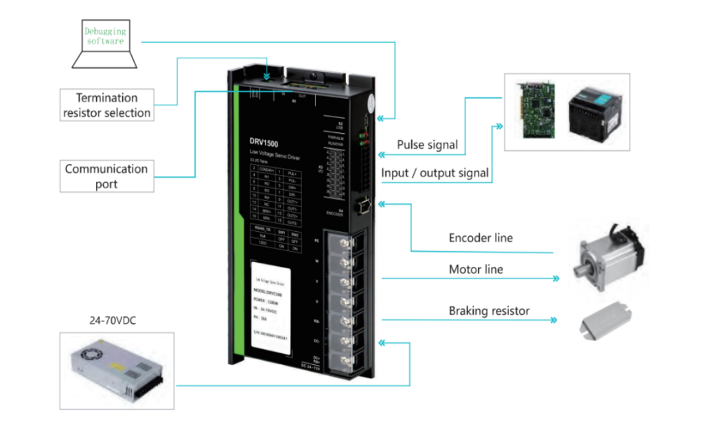
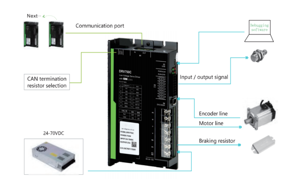
SIMTACH low voltage servo drives from 50W to 1.5Kw, support RS485 , EtherCAT,CANopen communication protocol.DRV series with high stable performance, quick positioning , and excellent anti-interference.
SIMTACH low voltage servo drives from 50W to 1.5Kw, support RS485 , EtherCAT,CANopen communication protocol.DRV series with high stable performance, quick positioning , and excellent anti-interference .



SIMTACH Low voltage servo drives from 50W to 1.5KW, support RS485,EtherCAT,CANopen communication protocol.DRV series with high stable performance, quick positioning , and excellent anti-interference .The servo controller will adjust the motor output signal according to the feedback signal and set parameters to achieve the purpose of accurate control.
| Main Function | |
|---|---|
| Power | 50W-1.5KW |
| Protection Class | IP10 |
| Power supply | 24-70VDC |
| Control mode | Speed,Position,Torque |
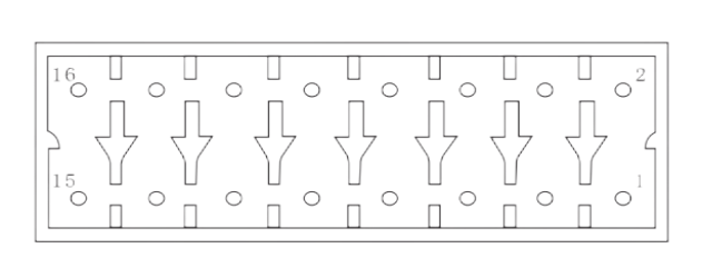
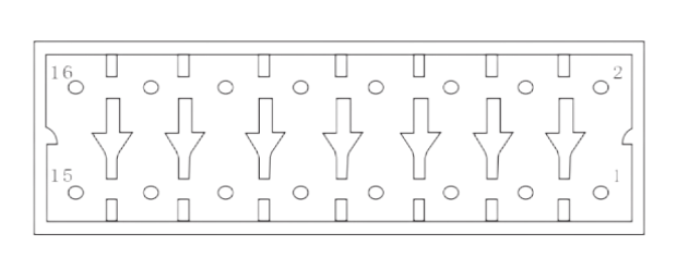
| Function | Signal | Pin number | Signal definition | Default Feature | lllustration |
|---|---|---|---|---|---|
| External pulse interface | PUL+ | 1 | Pulse positive | Position command signal | Signal terminals can accept 5V-24V signals,no need to connect resistors in series |
| PUL- | 3 | Pulse negative | |||
| DIR+ | 5 | Positive direction | |||
| DIR- | 7 | Negativedirection | |||
| Universal input interface | INCOM+ | 2 | Intput common port | 24V signal input | |
| IN1 | 4 | Input 1 | Servo enable | ||
| IN2 | 6 | Input 2 | Positive limit | ||
| IN3 | 8 | Input 3 | Negative limit | ||
| IN4 | 10 | Input 4 | Origin input | ||
| Universal output interface | OUT1+ | 9 | Output 1+ | Alarm output | |
| OUT1- | 11 | Output 1- | |||
| OUT2+ | 13 | Output 2+ | Return to zero complete | ||
| OUT2- | 15 | Output 2- | |||
| OUT3+ | 14 | Output 3+ | Brake output | It can be directly connected to the positive and negative signal terminals of the electromagnetic brake of the motor,without relay drive |
|
| OUT3- | 16 | Output 3- |
| Function | Signal | Pin number | Signal definition | Default Feature | lllustration |
|---|---|---|---|---|---|
| Universal input interface | INCOM+ | 2 | Intput common port | 24V signal input | |
| IN1 | 4 | Input 1 | Positive limit | ||
| IN2 | 6 | Input 2 | Negative limit | ||
| IN3 | 8 | Input 3 | Origin input | ||
| IN4 | 10 | Input 4 | Emergency stop | ||
| IN5+ | 1 | Input 5 | Probe 1 | ||
| IN5- | 3 | ||||
| IN6+ | 5 | Input 6 | Probe 2 | ||
| IN6- | 7 | ||||
| Universal output interface | OUT1+ | 9 | Output 1+ | Alarm output | |
| OUT1- | 11 | Output 1- | |||
| OUT2+ | 13 | Output 2+ | Return to zero complete | ||
| OUT2- | 15 | Output 2- | |||
| OUT3+ | 14 | Output 3+ | Brake output | It can be directly connected to the positive and negative signal terminals of the electromagnetic brake of the motor,without relay drive |
|
| OUT3- | 16 | Output 3- |